Namaste! I welcome you to explore my projects and work experience as you progress. My name is Sourabh Verma and I am a Mechanical Engineer.
About me
I am a Mechanical Engineer and automobile enthusiast, I hold a deep passion for the field. I obtained my undergraduate degree from Bangalore, India, and pursued a master's degree from NYU Tandon School of Engineering. A particular moment that has stayed with me was when Sebastian Vettel paid tribute to his Red Bull car (RB9) after winning the world driver championship in 2013. His display of respect for the machine made a lasting impression on me. From a young age, I was always curious about taking apart machines and examining their components, even if it meant potential scolding from my parents for not reassembling them properly. Pursuing Mechanical Engineering was a natural choice for me as it allowed me to expand my technical knowledge and skills.
During my undergraduate studies, I was fortunate enough to have access to various college clubs that allowed me to explore my passions. One of the clubs that caught my interest was the college automobile group, 'Team Enigma', where I took on the role of Head of the Brakes Department. I am grateful for the chance to represent my peers at national and international events as a member of this team. I have experience in robotics, having worked on projects like an Animatronic Hand, a Hexapod, and a stealth robot that can switch from a horizontal to a vertical surface without difficulty. Additionally, I gained valuable experience as an Operation Intern during the summer of 2022 with FIA Formula-E (Electric), where I led a team of over 180 members. It was a really unbelievable moment to work with FIA. Moreover, I had the opportunity to work as a Research Intern for the University of Massachusetts, Lowell in collaboration with NASA, the US Air Force, and Aurora Flight Science. I studied the structural behavior of composite micropillars subjected to transverse compression loading.
I love to read about the new technologies involved in the advancement of the automobile in my free time. I do spend time drawing the sketches as it allows me to concentrate more and makes me focused. I enjoy traveling to new places, going on hikes, and trying different cuisines. As a mechanical engineer, I constantly seek out solutions from diverse viewpoints. My curiosity is piqued by the intricate mechanics of Formula 1 racing, the re-entry of a space shuttle into our atmosphere, and the development of equipment that can prolong human life. These passions drive me daily to learn more.
Projects
Motorsports
Head of Brake Department / Team Captain/ Primary Driver
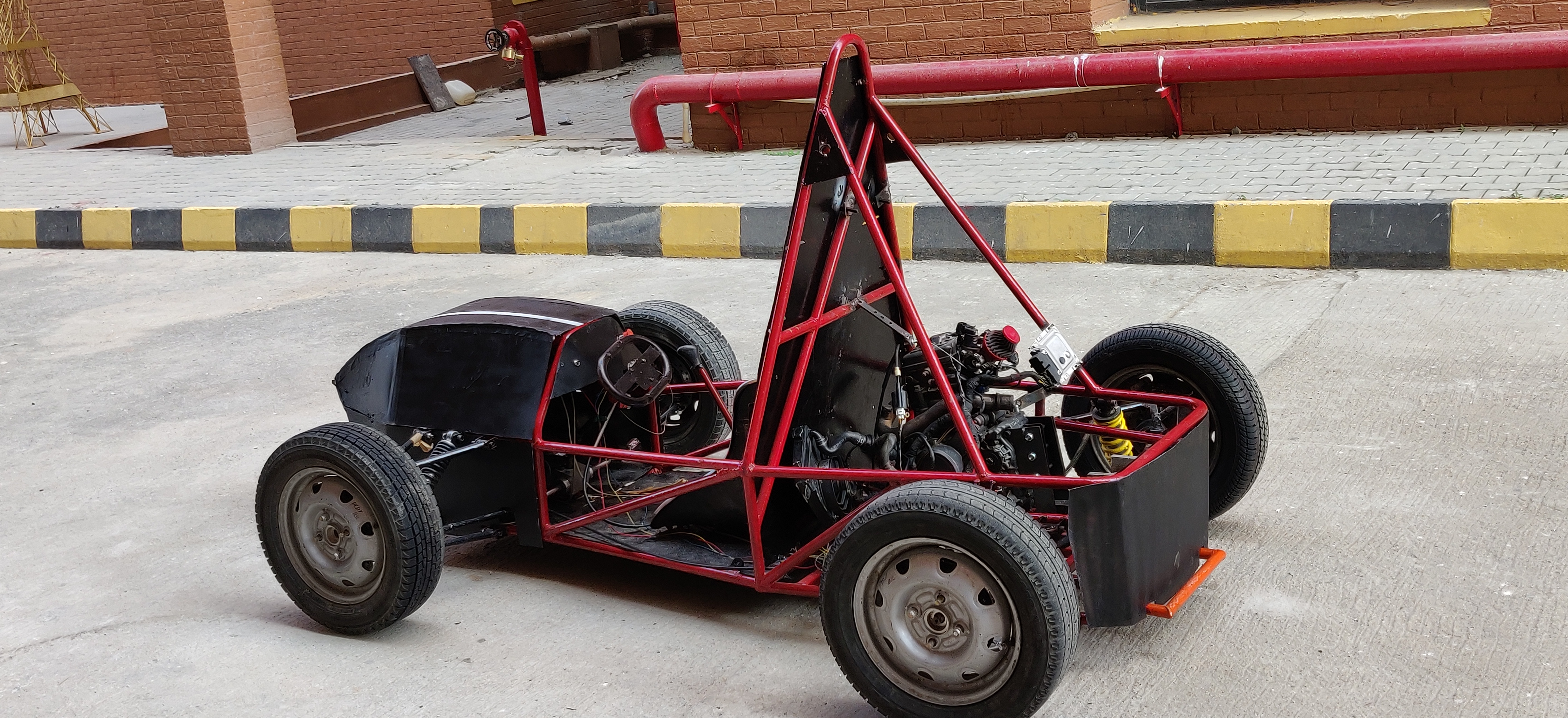
Society of Automotive Engineers BAJA (SAE - BAJA)
The all-Terrain Vehicle Competition is a national-level event that consists of a two-stage competition. In the first stage, teams present their vehicle designs, dynamics, and financial aspects. The second stage is an endurance round where teams manufacture a car that can perform on various terrains.
Brake Disc and another component development
Performed hand calculation for the Braking Torque and Force developed.
Produced the Brake Disc using CAD software SolidWorks.
Structural and thermal analysis of brakes was done using ANSYS software.
Mounting Plate for the assembly of the rack & pinion.
Material Procurement.
Brake Disc Design developed using SolidWorks
A tetrahedral mesh produced for better results
A static structural & steady-state thermal analysis was performed using ANSYS
Indian Society of Innovative Engineers - Hybrid Vehicle Competition (ISIE-HVC)
Student based formula racing competition held at international level. My role includes
Material Procurement
General Assembly & Fixation
Team Management
Aerospace Internship Projects
Mechanical Design Engineer Intern
AJAS
AJAS is a static test pad that was developed as part of the internship. STP is used to find the amount of thrust developed by the rocket motor. Access the design of the STP by clicking on the photo. The challenges I overcome in the production of STP are as follows
Weight was reduced from 25 kgs to 3kgs by using Aluminum 80-20.
Modular design which allows testing motor in both horizontal and vertical position.
Precise reading were obtained with the help of adjustable base.
Variable motor size can be achieved with the new motor clamp.
Load is equally distributed to all the legs when load is applied.
Max load = 350N and Max displacement = 0.1043mm
3 Ball point rocket motor clamp
Modular Design allows testing of a motor in 2 different orientations.
Structural analysis performed using Fusion 360
UDAAN
UDAAN is a low orbital space shuttle that was developed as part of the internship. The objective was to design the parachute ejection mechanism for the safe retrieval of the rocket body. Design can be seen by clicking the image
Robotics Project
Hexapod
Arduino controlled animatronic hand which can mimic the human hand motion.
Animatronic Hand
It is a six-legged robot having Arduino Uno, BT module, and servo motors to produce a similar motion to a spider.
Stress Analysis of Horizontal Pressure Vessel
Undergraduate Final Project
A comparative study was performed between 4 types of heads. A maximum of 12MPa of load is applied to the cylindrical vessel.
Hand calculation were performed and final computational values were compared.
CAD modelling was done using the SolidWorks.
Boundary Condition's base of the vessel is fixed and Internal pressure is 12MPa.
An ideal shape would be sphere to handle the pressure but from manufacturing point of view itis not possible. For that reason Cylindrical vessels with different heads are studied.
Static Structural Analysis was performed using ANSYS Workbench.
Material of all the cylindrical vessel is Carbon Steel [ASME SA 516 Grade 70/ASTM A516Grade 70].
Geometry of Vessels (SolidWorks)
Hemispherical Head
Torispherical Head
Flat Head
Analysis Phase of ellipsoidal head (ANSYS)
Ellipsoidal Head
Tetrahedral Mesh
Stress Analysis
Ellipsoidal Head is the preferred head connector among all the 4 head connectors for cylindrical vessels. Max Stress = 132.4MPa Max Displacement = 0.8mm
Micro-pillar Analysis
Research Intern with UMass, Lowell in collaboration with NASA, the US Air Force, and Aurora Space Science
The research was conducted to understand the structural behavior of the carbon fiber reinforced composite when subjected to compression loading in the transverse direction.
Micropillar were extracted from a composite and were subjected to compression loading.
Abaqus software was used to develop the model of the micropillar and analysis was alsoconducted using the same software.
MAC/GMC (Micromechanics Analysis Code with Generalized Method of Cells) softwarehelped in determining the composite nature in every direction.
Simulation aided to realize the failure originates from the interface of the polymer matrix and fiber.
Carbon fiber-reinforced Polymer IM7/5250-4
Fiber Reinforced Epoxy Composites
DFMA for Manual Food Chopper
Design for Manufacturability and Assembly was conducted using Boothroyd and Dewhurst Method
Manual food chopper is small equipment that can easily be found in the house kitchen. The objective was to make the assembly process more time efficient and reduce the manufacturing cost per piece.
With the help of the Boothroyd and Dewhurst method total assembly time came out to be 118 sec.
Performing critical part analysis yielded Assembly Efficiency (AE) =48.30%, Design Efficiency (DE) = 38.13%, and Per Count Design Efficiency (PCDE) = 78.95%.
Design for Environment which is a part of DFX helped in reducing the cost of chopper by 28%.
HyperLoop
Mechanical and CAD Team NYU
The working prototype of the hyperloop was produced. The objective was to design a structure strong a firm enough to hold the entire hyperloop firmly.
Validation of the support structure was done using the hand calculation and data obtained from the CAD Modelling.
SolidWorks aided to design the circular structure, middle support structure, pod and the track of the hyperloop.
ABS material was used to manufacture the support structure. The entire weight of the hyperloop was around 13.45kgs.


6.png)


